2021年 11月 の投稿一覧

Guide to “Copernican Revolution of Electromagnetism“BOOK Ⅸ New antenna theory and new magnet theory

preface

If you read each volume of the books that have been published so far, you can understand the fact that electromagnetic waves are a group of “electromagnetic elements” that are quantum beings, abandoning the conventional concept of electromagnetic waves.

Furthermore, as I emphasized in Volumes 3 and 8, I think you are convinced by the fact that even if the conductor is not directly connected to the power supply, an electric current will be generated if the “electromagnetic elements” comes into contact with the conductor.

It goes without saying that the same phenomenon occurs even in a direct current (or a square wave signal) in which the amount of the “electromagnetic elements” group does not change with time. This is also demonstrated in this book.

First, let’s talk about the antenna.

Considering the movement of the electromagnetic element group (mainly the magnetic field element in this case) on the transmitting antenna and the receiving antenna, it can be seen that direct current (square wave signal) can also be transmitted and received.

I have always emphasized that the electromagnetic element is divided into a magnetic field element and electronic field element.

Next is the magnet. Considering this matter, it seems that the electromagnetic element is composed of a magnetic field element and a electronic field element rather than being divided into a magnetic field element and a electronic field.

Then, the theory of “solar cells” will be overturned.

A “solar cell” has an antenna and receives sunlight (so to speak, alternating current), which is its ultra-short wave alternating current.

As I wrote in Volume 6, if it is received as it is, it will become zero volt due to multiple reflection by the antenna or the resistor at the electric wire part from the antenna.

After receiving the electromagnetic element group with the antenna, for example, if only the positive current is taken out immediately, even if this positive current is reflected multiple times, it becomes a positive direct current and the solar cell can function. 


Regarding magnetism, unlike the conventional theory, the current flowing through the coil flows symmetrically from the input end / output end to the coil, according to the theory of “Volume 4, New Capacitors and Coil”. Pushing forward with the fact, we can see that the electromagnetic element group is also functioning in the magnet. (Even after the current has been applied)

Afterword

Separating the “electromagnetic element” of the electromagnetic group into “magnetic field element” and “electronic field element”, and considering the movement of the “magnetic field element” on the antenna, I was able to construct a “new antenna theory“.

Although I have just started, I was able to construct a “new solar cell theory” by the same method for solar cells.

Furthermore, I was able to construct a “new magnet principle“.

When forming a magnet by passing a current through a general coil, the conventional theory was that the current flows unilaterally from the inlet to the outlet of the coil, but this is incorrect, and the coil inlet / outlet Positive / negative symmetric currents flow from both sides at the same time.

As a result, it will be as shown in the figure below.
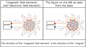
And finally, the positive / negative symmetric currents cancel each other out and the current becomes zero.

However, even if this current is interrupted, the “magnetic field elements” of these red and blue circles, in which “ferromagnets” are stored, still exert the “function of magnets“.

On the other hand, the “electronic field elements” exist in opposite directions (“red magnetic field element is inward” and “blue magnetic field element is outward”), and the total is zero volt, which is never detected by the external measurement system.

Therefore, the magnetic field from the magnet is an electromagnetic wave (a group of electromagnetic waves, a group of “magnetic fields”, and a group of electronic field element “). (The “electric field” is also generated from the “magnet”, but it is not observed.)

Regarding the fact that “magnetization exists even if the current is lost”, the fact that the “magnetic field” works without being affected by the outside should be considered as the same existence as gravity that works without being affected by the outside.


table of contents

Preface

Chapter 1 Electromagnetic waves are also generated from direct current 

Introduction Misunderstandings about magnetic fields and electric fields

Section 1 Square wave signal is also a DC signal

Section 2 The principle of the antenna is the principle of power generation

Chapter 2 Consideration using a dipole antenna

Introduction Experimental antenna

Section 1 Square wave signal transmission / reception experiment

Section 2 Remeasure “Measurement results: 1-4” in the previous section

Section 3 Elimination of reflection phenomenon between antenna and coaxial cable for power supply / reception

Supplement: 1 In the case of continuous pulse

Supplement: 2 Matching resistance

Supplement: 3 Reception status when the resistance value of the insertion resistor (“Fig .: 1”) is changed.

Supplement: 4 When the coaxial cable on the receiving side is changed to a feeder line

Section 4 Voltage status on the transmitting and receiving antennas

Supplement: One-terminal measurement of differential probe

Chapter 3 Reason why the length of the dipole antenna is 1/4 of the wavelength

From such a result, you can be convinced that the length of the dipole antenna is 1/4 of the wavelength.

 (Even in the case of “Reception antenna length: 50 cm each”, the reception condition is slightly better.)

Chapter 4 Construction of a new theory regarding antennas

Section 1 In the case of transmitting antenna

Section 2 In the case of receiving antenna

Chapter 5 Difference between 010 wave and 0110 wave

Chapter 6 Exploration of New Solar Cell Theory

Supplement: Slowing up and down of AC and direct current

Section 1 The first step of the new solar cell theory

       When there is only one receiving antenna and when there are two receiving antennas

Section 2 The second step of the empirical experiment of the new solar cell theory (Combining a diode with one antenna)

Chapter 7 New Magnet Principle

Introduction Doubts about how current flows through the coil of the conventional theory

Section 1 Inflow and outflow of current to the coil experiment in air)

Section 2 Examining the inside of the coil with an iron core coil instead of in the air

Section 3 Coil with more copper wire wound around the iron core

Section 4 Current and magnet flowing through the coil

Supplement: Magnetic field after turning off the power

Section 5 Hollow coil

Section 6 Conductor resistance

Item 1 The first cause of conductor resistance (reflection from diamagnetic material components in the conductor)

Item 2 The second cause of conductor resistance (depending on the ferromagnetic properties of the conductor)

Section 7 Electromagnetic field of iron core coil (while current is flowing)

 Supplement: Electromagnetic field of aluminum coil (while current is flowing)

Chapter 8 Electromagnetic element is magnetic field element and electronic field element

Chapter 9 Group of electromagnetic element and current

Chapter 10 Residual “group of electromagnetic element” population on iron core

Chapter 11 Role of magnetic field and electric field

Chapter 12 Superconductivity

Supplement: what is disappointed

Main measuring instruments used, etc.

 1 Pulse generator and function generator

 2 Oscilloscope

 3 SMA connector

 4 Differential probe

 5 EO (Electro-Optic-Sampling) probe

 6 Coaxial cable

 7 Parallel line: Red-black covered line

Afterword


For more detailed information,

please contact: Soubunsha

E-mail: info@soubunsha.com          

           tmt.usami@jcom.home.ne.jp

窓文社(SoubunshaWeb site

http://u33.sakura.ne.jp/soubunsyamakuji.htm

宇佐美保(Tamotsu Usami) Web site

http://u33.sakura.ne.jp/

Guide to “Copernican Revolution of Electromagnetism“ BOOK Ⅷ Supplement to tandem connection theory

In this book, the consideration in Chapter 11 of “Volume 3 Appearance of Tandem Connections” was insufficient and inappropriate, so further experimental measurements were repeatedly considered. I newly constructed a theory regarding the generation of negative reflected waves in the adjacent transmission line.

As a result, the adjacent transmission line and the signal line / ground line that composes the transmission line also become a transmission line that pairs with the signal line / ground line of the input transmission line.

It was clearly confirmed that the transmission lines were connected in parallel to the input transmission line while having a tandem connection relationship.

Furthermore, I have confirmed that this relationship also occurs in transmission line systems in which a dielectric is inserted between the signal line / ground line of each transmission line.(Generally, a transmission line system in which conductors are arranged on both sides of a glass epoxy substrate)

It was also found that an output signal with a voltage waveform having the same shape as the input signal can be obtained from the adjacent transmission line with a little work, without being limited to a specific frequency.

Furthermore,it was also confirmed that even with only one conductor instead of the adjacent transmission line of two conductors, a current flows through one conductor while being placed in the vortex of the electromagnetic field.

For this reason, you can clearly see that the electric current is not “the movement of electrons or electric charges in the conductor”, but “the electric current is a phenomenon that occurs as a result of the diamagnetic properties of the conductor and the collaborative work with the armature aggregate toward the conductor”. While conducting experimental measurements, we also pointed out the problems of grounding in power supplies that have grounding.

In order to explore the essence of electricity, we must first avoid the problem of grounding (eliminate “grounding”). However, at present, it is generally difficult to eliminate the ground, so in this book, voltage observation is performed using a differential probe (although this is still insufficient). 

In this book, I have re-examined “Chapter 11 Consideration on the generation of negative reflected waves in adjacent transmission lines” in “Volume 3, Appearance of Tandem Connections“.

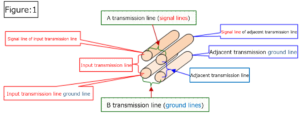
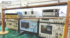
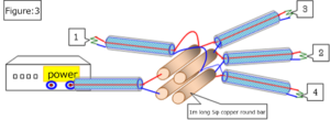
As in the previous work, use four copper round bars with a diameter of 5 mm and a length of 1 meter shown in “Photo: 1” and “Figure: 1” so that the characteristic impedance value of the input transmission line and the adjacent transmission line is 50Ω. Using a transmission line system with the conductor spacing (about 0.7 mm) adjusted, the results of experimental measurements and consideration were supplemented. (Similarly, the conductor spacing between the signal lines of both transmission lines and between the ground lines was set to about 0.7 mm.)


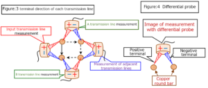
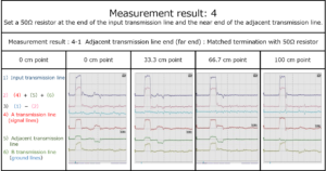
When inputting an electric signal from the power supply (pulse generator) to the input transmission line and measuring the voltage in each transmission line, the tip of the differential probe was touched as shown in “Figure: 3″ below. (The schematic diagram of this transmission line system corresponds to the state where “Fig .: 1” is viewed from the front. “A transmission line” is a transmission line formed by “input / adjacent transmission line signal lines”, and “B transmission line” is a transmission line formed by “input / adjacent transmission line ground lines”.


With three sets of transmission lines, “A transmission line”, “adjacent transmission line” and “B transmission line” connected in tandem, the voltage change of each transmission line is measured at the same time to the input transmission line. The fact that they are connected in parallel is demonstrated.

(Note: The simultaneity of each measurement result by one differential probe is ensured based on the time when the trigger current output from the pulse generator together with the input current reaches the oscilloscope.)


As you can see in this result, as confirmed in the previous book, you can see that

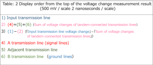
the voltage waveform (voltage value) of the input transmission line in 1) and the total location (that is, 2) of the three voltage waveforms of the A transmission line, the adjacent transmission line, and the B transmission line, which are in a Tandem connection relationship, are equal.

As a background to this, note that among the measurement results of 1) to 6), in particular, the displayed value (3) in the third row from the top of the displayed result is always zero.

(∵ (3)=(1)-(2)=0)

That is, (1): voltage waveform (voltage value) of “input transmission line” = (2): total value of voltage waveform (voltage value) of each “A, adjacent, B” transmission line

 Of course, on the adjacent transmission line, a voltage waveform having the same shape as the input transmission line and a voltage with a reverse phase waveform that cancels it are also generated.

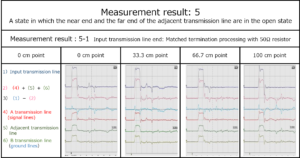
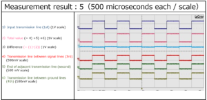
The following results can be obtained by applying current in the same way with the near and far ends of the adjacent transmission lines open.

“5) Adjacent transmission line”, “4) A transmission line” and “6) B transmission line” all observe “voltage waveform of the same shape as the input transmission line”, but the voltage of the opposite phase waveform is not generated.

However, in this state, the current generated in the adjacent transmission line cannot be carried out as it is.

But, in the following cases, it can be seen that a waveform with the same shape as the current input to the input transmission line can always be discharged.

Please see this book for the reason why this happens.

Afterword

transmission lines” in the appearance of tandem connection was insufficient, so by repeating further experimental measurements and reconsidering in this book. , I think that “Construction of tandem connection theory” has been completed.

Furthermore, as considered in “Chapter 6”, it was found that an event resulting from tandem connection occurred in “one transmission line” in addition to the adjacent transmission line.

The following can be seen from the results of these experimental considerations.

If an adjacent transmission line or other conductor is placed under the influence of a group of electromagnetic waves generated in the input transmission line, the newly placed conductor will form a transmission line with respect to the signal line or ground line of the input transmission line.This happens completely independently of “Faraday’s theory of electromagnetic induction“.

Then, it becomes clear that the current flows while maintaining the relationship of tandem connection and the relationship of parallel connection with the current of the input transmission line.

However, the state of these voltages is not clearly indicated by the oscilloscope, which is a conventional general voltage measuring instrument. (For details, refer to “Chapter 7, Section 2, When all terminals are connected to the oscilloscope“)

Faraday’s own words, which were quoted in Volume 3 and did not have as much measurement technology as they are now, are written as follows. “Although all currents always have a magnetic action of appropriate strength at right angles to their flow, a good conductor of electricity is induced in this range of action, and no current is induced in it. It seemed quite strange that it was not done, and that no such current-equivalent effect was perceived.

And “Faraday’s electromagnetic induction type” became common sense, and even if the current oscilloscope was used by the conventional method, it could not be overturned. Also, the superstition that “ground is always zero volt” has been established and continues to be believed.

Please read this book carefully and say goodbye to the superstitions of “Faraday’s electromagnetic induction” and “ground is zero volt”.


table of contents

Preface

Chapter 1 Current induced in adjacent lines

Introduction: Adjacent transmission lines are transmission lines that are connected in tandem and in parallel.

Section 1 Cause of reverse sign current flowing back from the end of the adjacent transmission line

Section 2 Changes in the current flowing through adjacent transmission lines due to changes in the ends of each transmission line

Item 1 When the near end of the adjacent transmission line is a 50Ω resistor and the end of the input transmission line is open.

Item 2 When the near end of the adjacent transmission line is a 50Ω resistor and the end of the input transmission line is short-circuited

Item 3 When the end of the input transmission line, lined up, and the end of the adjacent transmission line are 50Ω resistors

Item 4 When the input transmission line end is open and the adjacent transmission line end is a 50Ω resistor

Item 5 When the end of the input transmission line is short-circuited and the end of the adjacent transmission line is a 50Ω resistor

Item 6 When a resistor other than 50Ω is set at the end of the input transmission line

Section 3 Confirmation experiment in transmission line system using flat plate

Section 4 Prevention of negative backflow current in adjacent transmission lines

Section 5 Current generation status in transmission lines other than the input transmission line

Chapter 2 Signal waveforms similar to input lines can always be output externally from other transmission lines.

Section 1 Always output from adjacent lines to the outside

Supplement: Cause of the 10KHz waveform slightly deviating from the square wave in “Measurement result: 1 & 2”

Section 2 Development potential for DC transformers

Chapter 3 Actual conditions of crosstalk

Chapter 4 When splitting into an advanced wave and a backward wave

Chapter 5 Wiring with common ground wire (MSL board)

Chapter 6 When one conductor is installed next to the input transmission line instead of the transmission line

Chapter 7 Ground wire hides the essence of electricity here as well

Section 1 One transmission line to the oscilloscope

Section 2 When all terminals are connected to the oscilloscope

Section 3 Harmful effects of earth

Main measuring instruments used, etc.

1 Pulse generator and function generator

2 Oscilloscope

3 SMA connector

4 Differential probe

5 EO (Electro-Optic-Sampling) probe

6 Coaxial cable

7 Parallel line: Red-black covered line

Afterword


For more detailed information,

please contact: Soubunsha

E-mail: info@soubunsha.com          

           tmt.usami@jcom.home.ne.jp

窓文社(SoubunshaWeb site

http://u33.sakura.ne.jp/soubunsyamakuji.htm

宇佐美保(Tamotsu Usami) Web site

http://u33.sakura.ne.jp/


Guide to “Copernican Revolution of Electromagnetism“BOOK Ⅶ Misunderstanding about grounding

Many of those who have read up to Volume 6 of “The Copernican Revolution of Electromagnetism” respond as follows.

“Electricity goes on two wires at the same time with plus and minus”I never thought of such a phenomenon!   If you look at the chapters that follow, and even the entire series, you’ll be even more surprised!

I think that the background of this reaction is that when the readers of my books were studying the knowledge of electricity, the current differential probe did not exist and they used the resistance probe exclusively. (Maybe there is a better probe, and I hope it is, but the probe I use every day is a differential probe.) When I was a student, in experiments related to electricity, I used a “resistor probe” to measure the voltage between resistors, and I didn’t know the existence of other probes at all.

As you can see at a glance, “Comparison of measurement results with differential probe, resistance probe, and oscilloscope” on the back cover of this book, it’s no wonder that many people think, “I didn’t know that electricity runs two wires at the same time, plus or minus.“

Originally, the contents of this book should have been introduced as the first volume of the series, but there were other important experimental considerations, and it was necessary to break the conventional theory of coils and build a new theory. Because of that, I was put off.

Understanding that “electricity travels through two wires at the same time in plus and minus”, but if one of them has a long wire length, the longer wire operates as a “coil (pseudo coil)”. After that, I would like you to read this book.

This book makes it clear that the current theory of electricity is a theory constructed by ignoring “electricity goes on two electric wires at the same time with plus and minus”, and it is a tower on the sand.

Misunderstanding that the ground is zero volt

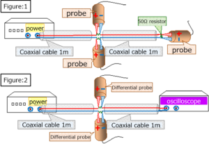
First, set a resistor (50Ω) on the ground line together with the signal line as shown in “Fig .: 1”, “Fig .: 2”, and “Fig .: 3” below.

In “Figure: 1” and “Figure: 3”, set it at the end as well. In “Figure: 2”, it is directly connected to the oscilloscope.

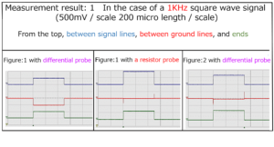
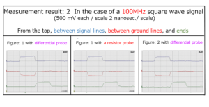
Then, a square wave signal (1V / 0V) was supplied from the power supply, and the voltage change between each resistor was measured with a differential probe.

(In “Figure: 1”, in addition to the differential probe, the resistance probe was also measured.)


Those who read this measurement result may think that “the measurement of the differential probe may be wrong”, but please refer to the text for the cause of the different measurement result.

In addition, please see the following experimental results.

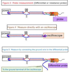
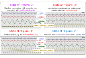
Using a coil of enamel wire wound 27 times around a ferrite bobbin as a signal line, connect a capacitor with two 1 cm wide and 2 meter copper foils bonded together with double-sided adhesive tape to the ground wire. The following shows the results of measuring the output waveforms in each case by passing sine waves (1V) of various frequencies in the state of the following “Fig .: 3 to 5“.(500 mV / scale for each 5 μsec / scale)

“Figure: 3” shows the case where the end of the output is matched and terminated with a 50Ω resistor and the output waveform is measured with a differential probe and a resistor probe.

“Figure: 4” is the case where the output cable is directly connected to the oscilloscope for measurement.

“Figure: 5” shows the case where one end of a 1-meter-long copper wire is connected to the negative terminal of the differential probe and the other end is led to the ground terminal of the oscilloscope.

Of the above measurement results, except for State of “Figure: 3”, you might think that the ground wire is always zero volt, but even if you set an element (capacitor in this case) on the ground wire, it has no influence. However, when the matching termination is performed with a resistor and measured with a differential probe in the “state of” Figire:3 “”, the influence of the capacitor set on the ground wire is clearly shown.

It is clear that the hint for elucidating why such a result is obtained is “Measurement with a differential probe with a state ground wire in” State of Figure: 5 “”.

I will post the afterword of the book.

Afterword

We still have to see the following commentary based on the recognition that the “ground wire is 0 volt“.


Single-ended transmission method

A method of connecting with two wires, a signal line and a ground line, and transmitting with a potential difference from the ground (0 volt).

Differential transmission method

A method in which two signal lines and one ground line (0 volt) are used for a total of three lines, and currents of opposite phases are passed through the two signal lines and transmitted by the potential difference between the signal lines.

However, if you read this book, I think that the vague concept of the ground has been clarified so far.

In this book, I have always stated that “0 volt ground wire is a misunderstanding”, but I hope you understand.

As described in the preface of this book, even those who read a series of this book series and were surprised that “I did not know until now that electricity travels two wires at the same time with plus and minus” Now that you have confirmed the background that you did not notice the facts, I think that you are fully convinced.

Calling the two lines (a set of conductors) that form a transmission line as a signal line and a ground line is very misleading, so it is necessary to consider those names separately.

For example, M line, W line, etc.

Transmission by one each of the conventional signal line and ground line (that is, M line and W line in the new name) should be differential transmission in nature.

I hope that new ways of using the ground line (W line) will be developed after clearly recognizing the fundamental character.

Of course, the “conventional electrical theory based on the perception that the ground wire is 0 volt” would of course have to be abandoned.

For details, please refer to this book.


table of contents

Chapter 1 Current flows from high potential to low potential

Section 1 Introduction to misunderstandings about grounding

Section 2 Electricity flows from low to high

Chapter 2 Misunderstanding about grounding

Section 1 Existence of pseudo grounding   transmission line

Item 1 Is an electric signal transmitted even with a single signal line?

Item 2 Misunderstanding that one ground wire is sufficient

Item 3 Connect the actual coil in parallel to the output terminal of the power supply

Section 2 Existence of pseudo ground wire (when an element is inserted in the ground wire)

Item 1 When a resistor is set on the ground wire

Item 2 When a capacitor is set on the ground wire

Section 3 Relationship between resonant circuit and  ground wire

Chapter 3 Cause of misunderstanding that the ground wire is zero volt

Chapter 4 Generation of pseudo-ground wire by electrical measuring equipment

Chapter 5 Harmful effects of grounding when measuring resistance probes

Section 1 Problems when measuring voltage between resistors

Section 2 Measure the relationship between the  resonant circuit and the ground wire with a resistor probe

Supplement 1 Relationship between the power supply voltage (Vo) and output voltage (V) of a power supply with an internal resistance of 50Ω

Supplement 2 Transmission line transmission and Ohm’s law

Chapter 6 grounding’s law when measuring various probes

Main measuring instruments used, etc.

 1 Pulse generator and function generator

 2 oscilloscope

 3 Resistance probe

 4 Differential probe

 4 EO (Electro-Optic-Sampling) probe

 5 Coaxial cable

Afterword


For more detailed information,

please contact: Soubunsha

E-mail: info@soubunsha.com          

           tmt.usami@jcom.home.ne.jp

窓文社(SoubunshaWeb site

http://u33.sakura.ne.jp/soubunsyamakuji.htm

宇佐美保(Tamotsu Usami) Web site

http://u33.sakura.ne.jp/

Guide to “Copernican Revolution of Electromagnetism“ BOOK Ⅵ alternating-current circuit theory is nothing but a house of cards

If you read the books “Volumes 1 to 5” so far, you can see that the recognition that “light has the dual character of waves and particles” was also the source of all misunderstandings about electricity.

Looking at “Measurement result: 1” on page 21 of “Volume 1, New Current Theory”,

a square wave signal of 20 MHz(for one cycle), which has a transmission time of only 25 nanoseconds ,extends to a state of 2 μs or more, that is, nearly 100 times as an output waveform to the end of a 600-meter cable.

From this result as well, it is difficult to see this 20MHz 1-pulse square wave signal as a single particle, as in the conventional particle theory.

Therefore, in “Volume 1” and later, the 1-pulse square wave signal and the 1-pulse (1 cycle) sine wave signal were also interpreted as an aggregate of “electromagnetic elements” (named by the author), which are quantum entities.

As described in Volume 1, Chapter 7, river waves and ocean waves reflect the “movement of one molecule of water” that composes them. Therefore, if we replace this “one molecule of water” with “one of the armatures”, we should be able to understand the behavior of electromagnetic waves more clearly.

As a result, I found that there is a “Tandem connection” (named by the author) in addition to the conventional “series connection” and “parallel connection” as the connection method of the electric circuit.

Introducing this concept reveals that both capacitors and coils are just “Tandem-connected transmission lines.”

As a result, it became clear that the current flowing through the capacitor and coil has a current flowing in the opposite direction as well as the input current direction.

(Of course, if there is a resistor in the transmission line, there is a current reflection phenomenon due to that resistor.)

Also, in “Volume 5 New Transformer Theory”,

 electricity is “proximity action”, so the transformer has no way of knowing

whether the current flowing into itself is “DC” or “AC”, and it turns out that the transformer works without distinction between direct current and alternating current.

(Similar results were obtained for capacitors in Volume 1)

Therefore, traditional electrical theories, especially those that specialize in alternating current, should be reviewed and need to be reconstructed.

As you all know, we are in the age of digital signals (square wave signals)!

Before reading this book, please read the following description, experiments, and calculation results.

“Misunderstanding of AC theory (resonant circuit): AC and direct current are the same electricity”

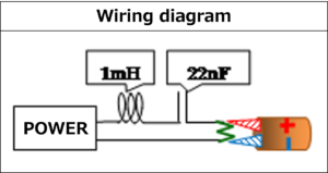
Connect the coil and capacitor in series to the signal line of the coaxial cable connected to the power supply as shown in the figure.

A terminating resistor (50Ω) was set at the output end of the coaxial cable, and measurement was performed with a differential probe. As a result, I confirmed the occurrence of the resonance phenomenon in the square wave signal.


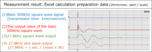
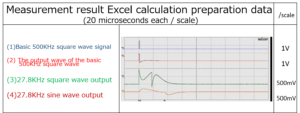
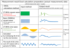
The following shows the measurement results of the output waveform when one pulse each of a 500KHz square wave signal and a sine wave signal (27.8KHz sine wave as a reference for the total result) is input to the circuit shown above. The result of adding up the output of the 500KHz square wave by the calculation software Excel is also shown below.This is the Excel method used in “Volume 5” and “Volume 1”.


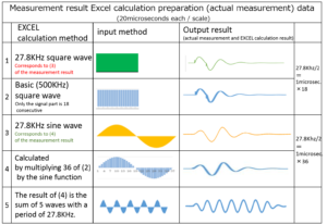
Looking at the result of this Excel, it becomes clear that  “the result of continuous summing of the output waveform of the 500KHz square wave signal based on this time every 1 microsecond, 27.8KHz square waveand the result of multiplying the output waveform of the basic square wave by the sine function every 1 microsecond and adding it up.match Measured value of sine wave output waveform“.

You might wonder, “Even if it matches the actual output waveform of a 27.8KHz sine wave, something is wrong because its shape looks different from the sine wave?“

The result of “The result of (4) is the sum of 5 waves with a period of 27.8KHz.”in the above measurement results clearly shows the sine wave shape at the summed points.

Of course, the same measurement results and calculation results can be obtained when “capacitors and coils are connected in parallel”.

The so-called “resonant circuit” is a misunderstanding even in the case of parallel connection.

As in the case of series connection, connect the coil and capacitor in parallel to the signal line of the coaxial cable connected to the power supply as shown in the figure below.

Set a terminating resistor (50Ω) at the output end of the coaxial cable.

With this device, as in the case of series connection, the output waveform when one pulse each of the basic 500KHz square wave signal and sine wave signal (27.8KHz sine wave as a reference for the total result) is input is differential. The result measured by the probe is shown. Here, the 1-pulse sine wave output wave does not have the shape of a sine wave.

Looking at the result of this Excel, it can be confirmed that the total result of the output waveform of the basic 500KHz square wave signal matches the measured value.

As you can see, the so-called “resonance phenomenon” is not a phenomenon peculiar to “AC: sine wave” regardless of whether it is connected in series or in parallel.

That is, alternating current and direct current are the same electricity.


Preface

Chapter 1 AC theory is the world of calculation

Section 1 Fracture of exchange theory

Section 2 Current and voltage phase shift is a misunderstanding

Section 3 Misunderstandings about resonant circuits

Item 1 Backflow current is generated from the capacitors and coils.

Item 2 When the capacitor and coil are connected in series

Item 3 When resistance is also involved

Item 4 Multiple reflection between each element and the length of the coupling part

Item 5 When a capacitor and a coil are connected in parallel

Item 6 Misunderstanding of LC circuit

Item 7 Coil (capacitor) characteristics are correlated with input / output transmission lines.

Chapter 2 Both the skin effect and Kelvin’s equation are misunderstood

Section 1 Proof that the skin effect is misunderstood

Supplement: 1 Multiple reflection phenomenon

Supplement: 2 Even now, in the age of experimental science

Section 2 Kelvin’s equation is also misunderstood

Supplement: 1 Relationship between the power supply voltage (V0) of a power supply with an internal resistance of 50Ω and the output voltage (V)

Supplement: 2 Presence or absence of frequency dependence of the flow of electrical signals

Section 3 Reconfirm multiple reflections in plus / minus waves

Chapter 3 Personal view of TV radio waves and X-rays

Afterword


For more detailed information,

please contact: Soubunsha

E-mail: info@soubunsha.com          

           tmt.usami@jcom.home.ne.jp

窓文社(SoubunshaWeb site

http://u33.sakura.ne.jp/soubunsyamakuji.htm

宇佐美保(Tamotsu Usami) Web site

http://u33.sakura.ne.jp/