2021年 10月 の投稿一覧

Guide to”Copernican Revolution of Electromagnetism“ BOOK Ⅴ New transformer theory

Faraday Electrical Experiment (Vol. 1) by M. Faraday, Supervisor: Toyosuke Tanaka” has the following description.


Even if a good electric conductor is placed in this working range, no current is induced in it.

It is strange that no effect equivalent to such an electric current is detected.

Considering these results, that is, expecting to obtain electricity from ordinary magnetism, encouraged me in various cases for the experimental study of the sensitive effect of electric current.

And recently I was able to reach a positive result.


When one pulse of a square wave signal was sent to the “capacitor or coil” in the state shown above, the following measurement results were obtained.

There was no way to know the existence of “electromagnetic waves” in Faraday,

which was before “Maxwell’s prediction of electromagnetic waves”.

In an attempt to obtain electricity from normal magnetism later in this quote, he would have focused on “magnetism only”.

Nevertheless, this attempt, apart from Faraday‘s initial expectations, evolved into a “great achievement” that created a practical “tranceformer” prototype. (See later “Chapter 9 Faraday’s own Trance Experiments” on this subject.)

Of course, as I have experimentally considered so far, “Faraday’s law of electromagnetic induction” is a product of misunderstanding, so the principle of transformer is naturally irrelevant to “Faraday’s law of electromagnetic induction”.

If the coil of the transformer is unwound, the wire is in a short state, but why does the transformer not emit fire? This has been a question I have had since I was a student.

When a square wave (direct current) with a frequency of 0.1 Hz (period is 10 seconds and transmission time is 5 seconds) is input to the transformer, the voltage at the coil entrance / exit of “Measurement result: 1” in “Chapter 2” later. Is 0 volt, so it is a fact that it is in a short state.

Since the input voltage in this experiment was 1 volt, the fire did not blow, but if it was 100 volt, it would have been a serious accident.

In this book, I will clarify whether the transformer that we use every day does not emit fire and functions properly as a transformer.

Before reading this book, please read the following description, experiments, and calculation results.

Transformer operation is basically direct current (square wave signal)

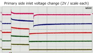
When only one pulse (1V / 0V) of a square wave with a different frequency is input to the primary coil of the transformer, the voltage waveform of the same shape as shown below can be obtained at the same time as the measurement result.

The measurement results of 0.1Hz, 10Hz, 50Hz, 250Hz, and 500Hz are shown in order from the top.


Furthermore, if the unit of the time axis is unified to 10 milliseconds per scale so that the entire 10 Hz (square wave) signal of one pulse is displayed, the following measurement results can be obtained.


From this measurement result, it can be seen that the operation of the transformer on the square wave signal is equivalent to the event that the DC input is stopped at a certain time during the operation by the DC input.

And if the input is restarted immediately after stopping the DC from this phenomenon, the DC input will be continued, and this operation will have the same result no matter how many times it is done..

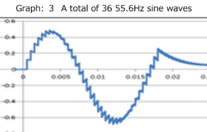
Therefore, it is possible to synthesize a long-period square wave signal such as “Graph: 2” from the result of the short-period square wave shown in “Graph: 1” as shown below. Furthermore, it is also possible to synthesize a sine wave signal such as “Graph: 3”.
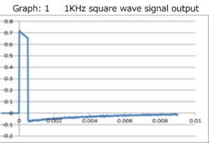
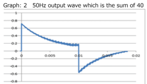


In “Graph: 3”, when adding up 36 pieces, the basic voltage value in Graph 1 is sin10 ° for the first pulse, sin20 ° for the second pulse, sin30 ° for the third pulse, and sin360 ° for the 36th pulse. The calculation was performed by multiplying the sine values ​​in sequence.


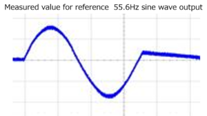
For reference, “measured value for reference” is also shown, but good matching with the total value is recognized.

Now, I will post a part of Chapter 10 of this book.

Chapter 10 Measurement Results on Copper Round Bar Transmission Lines Connected in Columns

In order to further solidify the theory that “the fundamental principle of transformers is columnar connection”, which has been elucidated in this book, “Chapter 11 Supplement: 3 Inputs and Adjacent” in the separate volume “Volume 3 Appearance of Columnar Connections” ,the experimental results shown in “When the terminal state of the transmission line is changed” are shown below.

Please refer to the separate volume “Volume 3” for details such as consideration of why such experimental results are obtained.

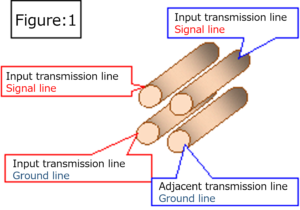
The experiment is carried out on an input transmission line as shown in “Fig. 1” consisting of four copper round bars with a length of 5 mm and a length of 1 meter, and an adjacent transmission line connected in tandem to the input transmission line.

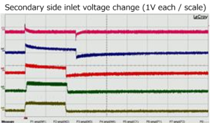
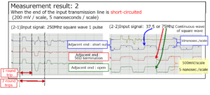
In the experiment, when the end of the input transmission line was matched and terminated with a 50Ω resistor, it was changed to three states: a short state and an open state, and the end treatment of the adjacent transmission line was also shorted accordingly. It is performed by changing to the 50Ω termination processing state and the open state. In each case, a continuous wave of 250MHz (1V / 0V) 1-pulse square wave and 75MHz (in some cases 37.5MHz) square wave is input from the pulse generator to the input transmission line, and the near end of the adjacent transmission line. The voltage change of the part was measured with a differential probe, and the following results were obtained.


First, the measurement results for the transmission line shown in “Figure: 1” when the end of the input transmission line is matched and terminated with a 50Ω resistor are shown.
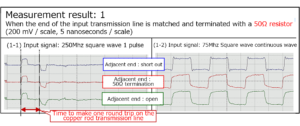


Next, the following shows the measurement results on the adjacent transmission line when the end of the input transmission line is short-circuited.
 

The last is the measurement result on the adjacent transmission line when the end of the input transmission line is open.


The following can be seen from these measurement results.

There is a phenomenon in which a current of the same shape as the input current is induced by the current input to the input transmission line to both the near end and the far end of the adjacent transmission lines that are in a columnar connection relationship.

The current toward the far end flows back as a negative or positive current depending on the conditions at the far end of the input transmission line and the adjacent transmission line.

If the end of the input transmission line is not terminated, the backflow current generated in the input transmission line causes a new current to be generated in the adjacent transmission line at the input section of the input transmission line.

These phenomena are caused by the columnar connections that have been experimentally considered so far, and are equivalent to the “considerations regarding the generation of negative reflected waves in adjacent transmission lines” discussed in this chapter.

Of course, depending on the terminal condition of the input transmission line or the method of eliminating the column connection, a positive wave may be generated instead of a negative reflected wave on the adjacent transmission line.

From such a simple experiment and an experiment of the transmission line structure including the case where the ends of the input transmission line and the adjacent transmission line are short-circuited like the coil, it becomes clear that the basic principle of the transformer is the column connection.


table of contents

Preface

Chapter 1 Contradiction between transformer operation and “Faraday’s law of electromagnetic induction”

Chapter 2 Transformers also work with square wave signals

Chapter 3 Check the operating status of the transformer with a square wave signal

Chapter 4 Transformer operation is basically a DC signal (square wave signal)

Chapter 5 Confirm the operation of the transformer based on the DC signal (square wave signal) with calculation software

Chapter 6 Similarity between a single coil and a transformer

Chapter 7 Reconfirmation of similarity between transformer and single coil

Chapter 8 Measurement results using another transformer

Chapter 9 Relationship between transformer and continuous wave

Chapter 10 Measurement Results on Copper Round Bar Transmission Lines Connected in Columns

Chapter 11 Examination of general electric wires as circular transmission lines

Chapter 12 Coil general electric wires

Chapter 12 Section 1 Multiple coil effects

Chapter 12 Section 2 Effects of core materials

Chapter 13 Faraday’s own trance experiment

Chapter 14 Role of core materials in transformers

Chapter 14 Section 1 When ferrite is used for the transformer core

Supplement: Measurement of only the positive terminal of the differential probe

Chapter 14 Section 2 Effect of ferrite on transmission lines

Chapter 14 Section 3 Preliminary Experiments Using Permalloy

Chapter 15 Relationship between transformer input / output voltage and coil turns ratio

Chapter 16 An example of general recognition of transformers

Chapter 17 Transformer power loss

Chapter 17 Section 1 Loss inside the transformer

Chapter 17 Section 2 Loss during power transmission

Chapter 18 DC transformer

Afterword


For more detailed information,

please contact: Soubunsha

E-mail: info@soubunsha.com          

           tmt.usami@jcom.home.ne.jp

窓文社(SoubunshaWeb site

http://u33.sakura.ne.jp/soubunsyamakuji.htm

宇佐美保(Tamotsu Usami) Web site

http://u33.sakura.ne.jp/

Guide to”Copernican Revolution of Electromagnetism“ BOOKⅣ A new theory of capacitors and coils

According to conventional electrical theory and common wisdom, “capacitors” and “coils” are regarded as “electronic components” that have no similarities.

First of all, if you look at the figures and measurement results shown below, you will understand the subtitle of this book, “Capacitors and coils are transmission lines connected in tandem.“


Both the capacitor and the coil are transmission lines that are connected in tandem.


When one pulse of a square wave signal was sent to the “capacitor or coil” in the state shown above, the following measurement results were obtained.


From this measurement result that (3) becomes a square wave or zero state, the absolute value is the same from the “capacitor or coil” to the input side / output side transmission line, and the current with the opposite sign is discharged. The phenomenon becomes clear.

And from this result, it is clear that both the capacitor and the coil are transmission lines connected in tandem.

You can see that the “current flowing through the capacitor” is definitely not the “displacement current” that appears in the “Maxwell’s equations” that was firmly believed until now.

Furthermore, you can understand that the current flowing through the coil does not flow in sequence for each coil.

Please see this book for details on experiments and considerations on new electrical theories related to capacitors and coils.

I will describe the table of contents of this book, but in the following part, I prove that the treditional theory is misunderstood about things other than coils and capacitors.

“Chapter1 Section5 Supplement Misunderstanding of inrush current related to capacitors”

“Chapter2 Section6Elimination of misunderstandings about inductance”

“Chapter2 Section7Inductance Misunderstanding: In the case of parallel connection type coil”

“Chapter2 Section9 Line capacitance is a misunderstanding, in fact multiple reflections”


Table of contents

Preface

Chapter 1 New Capacitor Theory

Section 1 Capacitors are vertically connected transmission lines

Supplement: Internal voltage change type of filter type capacitor

Section 2 Image of input / output status to capacitor transmission line

Section 3 Supplement to the image of the input / output status to the capacitor transmission line

Supplement: Further supplement the image with the actual measurement results

Section 4 Comparison of measured and calculated values ​​of voltage changes in capacitors

Supplement: Comparison of measured and calculated values ​​of voltage changes in copper foil capacitors

Section 5 Introduction of bypass type capacitor transmission line

Supplement: Misunderstanding of inrush current related to capacitors

Section 6 The low Z transmission line connected in series is a bypass type capacitor.

Section 7 Current status of commercially available capacitors

Chapter 2 New Coil Theory

Section 1 Coil is a transmission line connected in columns

Section 2 Difference between coil transmission line and capacitor transmission line

Section 3 Image of input / output status to coil transmission line

Section 4 Supplement to the input / output status image to the coil transmission line

Section 5 Actually measure and confirm the input / output status to the coil transmission line

Section 6 Elimination of misunderstandings about inductance

Section 7 Inductance Misunderstanding: In the case of parallel connection type coil

Supplement: Mathematical consideration of parallel connection coils

Section 8 Series connection type coil (series coil)

Section 9 Line capacitance is a misunderstanding, in fact multiple reflections

Afterword


For more detailed information,

please contact: Soubunsha

E-mail: info@soubunsha.com          

           tmt.usami@jcom.home.ne.jp

窓文社(SoubunshaWeb site

http://u33.sakura.ne.jp/soubunsyamakuji.htm

宇佐美保(Tamotsu Usami) Web site

http://u33.sakura.ne.jp/

Guide to “Copernican Revolution of Electromagnetism“ BOOKⅢ Introducing tandem connections

In “Faraday Electric Experiment”, Faraday left the following description


Based on the magnet results I had obtained up to this point, the battery current through one wire actually produces the same current in the other wires, but lasts only for a moment. Yes, rather than the current of a Voltaic battery, it has the property of an electric wave passing by the impact of an ordinary Leyden jar, so it barely works on a galvanometer, but it magnetizes the steel needle. I believed that I must be able to do it.

I was taught that the “current that lasts only for a moment in other wires” in this Faraday description is commonly referred to as “crosstalk.“

However, if Faraday conducted an experiment with the idea of ​​Copernican Revolution using the current electrical measuring equipment that he could not use even if he wanted to use it, the “current flow state between the two wires” was not abnormal at all. It turns out to be suitable for.

Further experiments reveal that the adjacent line next to the input line also has a current similar to the current flowing through the input line.

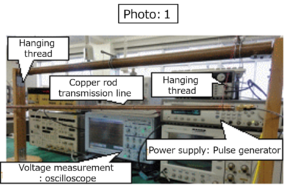
Therefore, using copper round bars, I created input transmission lines and adjacent transmission lines as shown in “Figure: 1” and “Photo: 1” using four copper round bars with a length of 5 mmφ and a length of 1 meter.


The conductor spacing was adjusted so that the characteristic impedance value of each transmission line was also 50Ω, and the end of each transmission line (Z = 50Ω of each transmission line) was subjected to 50Ω matched termination processing.

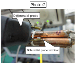
The rear part of the adjacent transmission line (opposite the direction of travel of the input signal) is extended by about 4 cm with a coaxial cable, and the end is subjected to 50Ω matched termination processing, and the current induced in the adjacent transmission line is applied. Measured using a differential probe (“Photo: 2”) and an oscilloscope.


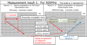
One pulse of a 500MHz square wave signal is input from the pulse generator to this input transmission line, and the progress (voltage change) is measured at each part of the input transmission line (points 0, 33.3, 66.7, 100 cm). Was measured and “Measurement result: 1-1” was obtained.

Furthermore, the electric signal toward the near end (Note) obtained by extending the rear part of the adjacent adjacent transmission line by about 4 cm with a coaxial cable (at the point of minus 4 cm), and the electric signal toward the far end (Note) are 0. , 33.3, 66.7, and 100 cm were measured using a differential probe, and the following “measurement result: 1-2” was obtained.

Note: Generally, in the adjacent transmission line, the input side of the input transmission line is called the near end, and the end side of the input transmission line is called the far end


What should be noted in this measurement result is that electric signals of the same shape are simultaneously traveling at the electromagnetic wave velocity in the air on both the 1-meter long input and adjacent transmission lines installed in the air.

Furthermore, at the far end of the adjacent transmission line, the far end crosstalk reverses the sign and flows back to the near end side as a negative signal. (Round trip time: Approximately 6.7 nanoseconds = 3.3 nanoseconds x 2)

At the end (far end) of the adjacent transmission line, the plus / minus signals cancel each other out.

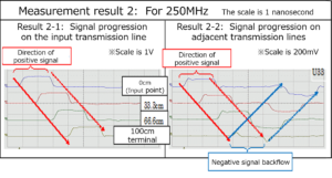
Furthermore, even if the frequency of the input signal is changed and the same measurement is performed, this situation does not change. “In the adjacent transmission line, the positive and negative of the signal waveform toward the far end is reversed at the far end, and a negative signal is sent to the near end. The phenomenon of “backflow” is observed one after another, and the process leading to “misunderstanding of Faraday” becomes clear.

For example, in the case of 250MHz (1V / 0V), the measurement situation is, of course, the same in the case of 500MHz..


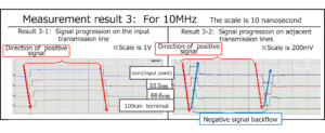
Next, the measurement results for 10MHz are shown below.


The waveform shape seen in this result (the progress of the signal in the adjacent transmission line) is a little similar to Faraday’s misunderstanding of “Faraday’s electromagnetic induction phenomenon”.

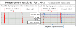
Furthermore, in the case of 1MHz, which has a long wavelength, observation results that can be mistaken for “Faraday’s electromagnetic induction phenomenon” itself can be obtained.


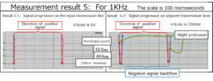
Next, the following is the case of 1KHz.


I can get observation results that are completely mistaken for “Faraday’s electromagnetic induction phenomenon” itself, but if you observe the waveforms observed at the near end on the same time axis, they are all the same waveform.

It is natural to observe the same waveform change as in these cases in the voltage waveform change at the input section when the input transmission line is short-circuited at the end.

And from the measurement results so far, it can be seen that “Faraday’s electromagnetic induction theory” is a product of misunderstanding.

So why does the adjacent line (adjacent transmission line) carry the same electrical signal as the input line (input transmission line)?

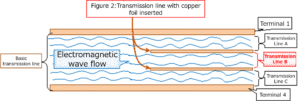
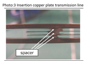
As shown in Chapter 4 “Is the bearer of current a charge?” In Volume 1 “New Current Theory”, the following “Figure: 2” and “Photo: 3” transmission line system Since electric signals of the same shape flow through each transmission line, as described in “Fig .: 2”, “the current bearer is not the electric charge, but the flow of electromagnetic waves, that is, the flow of the electromagnetic group”, and each of them This is because the transmission lines are in a pile connection relationship.


So why do the same types of electrical signals flow through transmission lines that are in a “pile connection” relationship?

Please see this book about this matter.


Table of contents

Preface

Chapter 1 Solve Faraday’s misunderstandings with current measuring instruments

Chapter 2 Current Induced on Adjacent Lines

Chapter 3 A signal of the same shape as the input signal also flows in the adjacent transmission line.

Supplement: When the near end side of the adjacent transmission line is extended

Chapter 4 A signal that cancels a signal of the same shape as the input signal also flows on the adjacent line.

Supplement: 1 When the terminal state of the “adjacent transmission line” is changed

Supplement: 2 For input signals other than square waves

Chapter 5 Solving “Faraday’s Misunderstanding” Using General Electric Wires

Supplement: Measurement of transmission lines with characteristic impedance values ​​other than 50Ω (matching resistance)

Chapter 6 Appearance of column connection

Chapter 7 Birth of Column Connection

Supplement Development of DC transformer utilizing column joining

Chapter 8 Deploying Column Connections

Chapter 9 Combined Characteristic Impedance of Column-Connected Transmission Lines

Supplement: Series connection of resistors is equivalent to column connection

Chapter 10 The currents flowing in the column connection transmission line have the same value.

Chapter 11 Consideration on the generation of negative reflected waves on adjacent transmission lines

Supplement: 1 If the relationship with the input transmission line is estranged, a current with the opposite sign will flow backward.

Supplement: 2 Characteristic impedance value of transmission lines connected in parallel in parallel

Supplement: 3 When the terminal state of the input line and adjacent transmission line is changed

Chapter 12 Displacement current is also a product of misunderstanding

Chapter 13 Why people haven’t noticed “Faraday’s misunderstanding” for many years

Section 1 Cause of splitting into advanced wave and backward wave

Section 2 Verification of the cause of splitting into advanced and backward waves (1)

Section 3 Verification of the cause of splitting into advanced and backward waves (2)

Afterword

Main measuring instruments used, etc.


For more detailed information,

please contact: Soubunsha

E-mail: info@soubunsha.com          

           tmt.usami@jcom.home.ne.jp

窓文社(SoubunshaWeb site

http://u33.sakura.ne.jp/soubunsyamakuji.htm

宇佐美保(Tamotsu Usami) Web site

http://u33.sakura.ne.jp/

Guide to “Copernican Revolution of Electromagnetism“ BOOKⅡ New power generation theory

In the previous “Volume 1 New Current Theory”, I have experimentally proved the fact that “current is not the transfer of electric charge”.

However, the “Maxwell’s equations” that underpins the current “electromagnetism” unfortunately develops the “current is the charge transfer theory”.

First of all, “This is physics! (Written by Professor W. Lewin of Massachusetts Institute of Technology, translated by Kazuki Agarie, published by Bungei Shunju) ”sees the following description

In my electrical and magnetic course, once I’ve learned all of Maxwell’s equations in perfect beauty and simplicity, I’ll project them throughout the auditorium to show students this important and groundbreaking event. Celebrate together by handing flowers …

Furthermore, please see the following description in “Feynman Physics III, translated by Tatsunori Miyajima: published by Iwanami Shoten”.


The center of the electromagnetic world is here. A complete theory of electricity, magnetism, and light-a complete description of the field of moving charges. It’s all here. Here is Maxwell’s building, completed in terms of power and beauty. This is probably one of the greatest successes of physics. To remember its importance, put it together and put it in a clean frame.

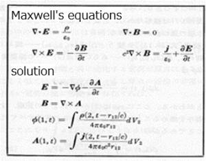
Maxwell's equations

Furthermore, please see the description of “The Concept of Electromagnetics: Shigenobu Sunakawa: Author, Iwanami Shoten: Published”.


This Maxwell’s equation is the main pillar of classical physics that is on par with Newton’s equation of motion.

Many physicists believe that the basic laws of physics must be beautiful in shape. And “beauty” is one of the guiding principles of physics research. A typical example is Einstein. Do you think Maxwell’s equations are beautiful? If so, I have the potential to become a physicist.


Many people still continue to praise the “Maxwell’s equations” that was built in affirmation of “current is the transfer of electric charge” buried in the previous “Volume 1”, as in the above praise.

In particular, no one has ever doubted the “Faraday’s law” (change in the magnetic field in the coil causes current to be generated in the coil) as “Equation: 3” as the “principle of power generation”.

However, in M. Faraday’s own book, “Faraday Electric Experiments,” which laid the foundation for this mathematical formula and is said to be the “father of electricity,” Faraday’s own creative experiments and excellent consideration for them without seeing the mathematical formulas. Is described.

When I experiment and consider using the current electrical measuring equipment again, we can see that the mathematical formula “Formula: 3” was constructed by misunderstanding Faraday’s experimental consideration.

The “Maxwell’s equations” that everyone still worships are easily broken down.

Then, I will describe in this book the aspect of being rewritten from my own experimental consideration to a new “principle of power generation”.

It was Faraday’s coined word “diamagnetism” that led me to this new “principle of power generation”, as in the case of “Volume 1 New Current Theory”, and Faraday’s foresighted “” Electricity was a proximity action. “