In “Faraday Electric Experiment”, Faraday left the following description
| Based on the magnet results I had obtained up to this point, the battery current through one wire actually produces the same current in the other wires, but lasts only for a moment. Yes, rather than the current of a Voltaic battery, it has the property of an electric wave passing by the impact of an ordinary Leyden jar, so it barely works on a galvanometer, but it magnetizes the steel needle. I believed that I must be able to do it. |
I was taught that the “current that lasts only for a moment in other wires” in this Faraday description is commonly referred to as “crosstalk.“
However, if Faraday conducted an experiment with the idea of Copernican Revolution using the current electrical measuring equipment that he could not use even if he wanted to use it, the “current flow state between the two wires” was not abnormal at all. It turns out to be suitable for.
Further experiments reveal that the adjacent line next to the input line also has a current similar to the current flowing through the input line.
Therefore, using copper round bars, I created input transmission lines and adjacent transmission lines as shown in “Figure: 1” and “Photo: 1” using four copper round bars with a length of 5 mmφ and a length of 1 meter.
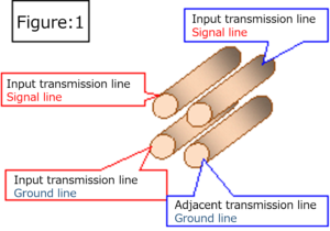
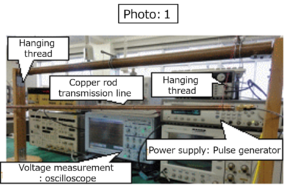
The conductor spacing was adjusted so that the characteristic impedance value of each transmission line was also 50Ω, and the end of each transmission line (Z = 50Ω of each transmission line) was subjected to 50Ω matched termination processing.
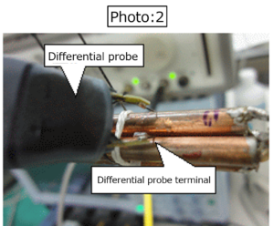
The rear part of the adjacent transmission line (opposite the direction of travel of the input signal) is extended by about 4 cm with a coaxial cable, and the end is subjected to 50Ω matched termination processing, and the current induced in the adjacent transmission line is applied. Measured using a differential probe (“Photo: 2”) and an oscilloscope.
One pulse of a 500MHz square wave signal is input from the pulse generator to this input transmission line, and the progress (voltage change) is measured at each part of the input transmission line (points 0, 33.3, 66.7, 100 cm). Was measured and “Measurement result: 1-1” was obtained.
Furthermore, the electric signal toward the near end (Note) obtained by extending the rear part of the adjacent adjacent transmission line by about 4 cm with a coaxial cable (at the point of minus 4 cm), and the electric signal toward the far end (Note) are 0. , 33.3, 66.7, and 100 cm were measured using a differential probe, and the following “measurement result: 1-2” was obtained.
Note: Generally, in the adjacent transmission line, the input side of the input transmission line is called the near end, and the end side of the input transmission line is called the far end
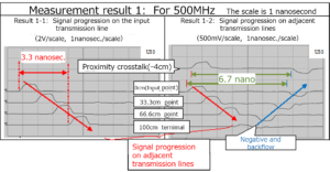
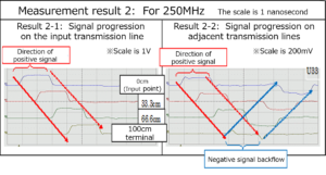
What should be noted in this measurement result is that electric signals of the same shape are simultaneously traveling at the electromagnetic wave velocity in the air on both the 1-meter long input and adjacent transmission lines installed in the air.
Furthermore, at the far end of the adjacent transmission line, the far end crosstalk reverses the sign and flows back to the near end side as a negative signal. (Round trip time: Approximately 6.7 nanoseconds = 3.3 nanoseconds x 2)
At the end (far end) of the adjacent transmission line, the plus / minus signals cancel each other out.
Furthermore, even if the frequency of the input signal is changed and the same measurement is performed, this situation does not change. “In the adjacent transmission line, the positive and negative of the signal waveform toward the far end is reversed at the far end, and a negative signal is sent to the near end. The phenomenon of “backflow” is observed one after another, and the process leading to “misunderstanding of Faraday” becomes clear.
For example, in the case of 250MHz (1V / 0V), the measurement situation is, of course, the same in the case of 500MHz..
Next, the measurement results for 10MHz are shown below.
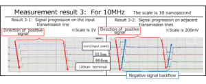
The waveform shape seen in this result (the progress of the signal in the adjacent transmission line) is a little similar to Faraday’s misunderstanding of “Faraday’s electromagnetic induction phenomenon”.
Furthermore, in the case of 1MHz, which has a long wavelength, observation results that can be mistaken for “Faraday’s electromagnetic induction phenomenon” itself can be obtained.
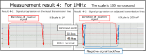
Next, the following is the case of 1KHz.
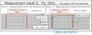
I can get observation results that are completely mistaken for “Faraday’s electromagnetic induction phenomenon” itself, but if you observe the waveforms observed at the near end on the same time axis, they are all the same waveform.
It is natural to observe the same waveform change as in these cases in the voltage waveform change at the input section when the input transmission line is short-circuited at the end.
And from the measurement results so far, it can be seen that “Faraday’s electromagnetic induction theory” is a product of misunderstanding.
So why does the adjacent line (adjacent transmission line) carry the same electrical signal as the input line (input transmission line)?
As shown in Chapter 4 “Is the bearer of current a charge?” In Volume 1 “New Current Theory”, the following “Figure: 2” and “Photo: 3” transmission line system Since electric signals of the same shape flow through each transmission line, as described in “Fig .: 2”, “the current bearer is not the electric charge, but the flow of electromagnetic waves, that is, the flow of the electromagnetic group”, and each of them This is because the transmission lines are in a pile connection relationship.
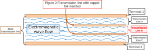
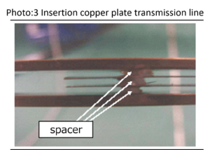

So why do the same types of electrical signals flow through transmission lines that are in a “pile connection” relationship?
Please see this book about this matter.
Table of contents
Preface
Chapter 1 Solve Faraday’s misunderstandings with current measuring instruments
Chapter 2 Current Induced on Adjacent Lines
Chapter 3 A signal of the same shape as the input signal also flows in the adjacent transmission line.
Supplement: When the near end side of the adjacent transmission line is extended
Chapter 4 A signal that cancels a signal of the same shape as the input signal also flows on the adjacent line.
Supplement: 1 When the terminal state of the “adjacent transmission line” is changed
Supplement: 2 For input signals other than square waves
Chapter 5 Solving “Faraday’s Misunderstanding” Using General Electric Wires
Supplement: Measurement of transmission lines with characteristic impedance values other than 50Ω (matching resistance)
Chapter 6 Appearance of column connection
Chapter 7 Birth of Column Connection
Supplement Development of DC transformer utilizing column joining
Chapter 8 Deploying Column Connections
Chapter 9 Combined Characteristic Impedance of Column-Connected Transmission Lines
Supplement: Series connection of resistors is equivalent to column connection
Chapter 10 The currents flowing in the column connection transmission line have the same value.
Chapter 11 Consideration on the generation of negative reflected waves on adjacent transmission lines
Supplement: 1 If the relationship with the input transmission line is estranged, a current with the opposite sign will flow backward.
Supplement: 2 Characteristic impedance value of transmission lines connected in parallel in parallel
Supplement: 3 When the terminal state of the input line and adjacent transmission line is changed
Chapter 12 Displacement current is also a product of misunderstanding
Chapter 13 Why people haven’t noticed “Faraday’s misunderstanding” for many years
Section 1 Cause of splitting into advanced wave and backward wave
Section 2 Verification of the cause of splitting into advanced and backward waves (1)
Section 3 Verification of the cause of splitting into advanced and backward waves (2)
Afterword
Main measuring instruments used, etc.
| For more detailed information,
please contact: Soubunsha E-mail: info@soubunsha.com 窓文社(Soubunsha)Web site http://u33.sakura.ne.jp/soubunsyamakuji.htm 宇佐美保(Tamotsu Usami) Web site |
Recent Comments