Many of those who have read up to Volume 6 of “The Copernican Revolution of Electromagnetism” respond as follows.
“Electricity goes on two wires at the same time with plus and minus”I never thought of such a phenomenon! “ If you look at the chapters that follow, and even the entire series, you’ll be even more surprised!
I think that the background of this reaction is that when the readers of my books were studying the knowledge of electricity, the current differential probe did not exist and they used the resistance probe exclusively. (Maybe there is a better probe, and I hope it is, but the probe I use every day is a differential probe.) When I was a student, in experiments related to electricity, I used a “resistor probe” to measure the voltage between resistors, and I didn’t know the existence of other probes at all.
As you can see at a glance, “Comparison of measurement results with differential probe, resistance probe, and oscilloscope” on the back cover of this book, it’s no wonder that many people think, “I didn’t know that electricity runs two wires at the same time, plus or minus.“
Originally, the contents of this book should have been introduced as the first volume of the series, but there were other important experimental considerations, and it was necessary to break the conventional theory of coils and build a new theory. Because of that, I was put off.
Understanding that “electricity travels through two wires at the same time in plus and minus”, but if one of them has a long wire length, the longer wire operates as a “coil (pseudo coil)”. After that, I would like you to read this book.
This book makes it clear that the current theory of electricity is a theory constructed by ignoring “electricity goes on two electric wires at the same time with plus and minus”, and it is a tower on the sand.
Misunderstanding that the ground is zero volt
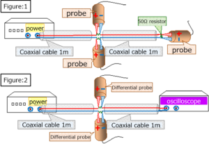
First, set a resistor (50Ω) on the ground line together with the signal line as shown in “Fig .: 1”, “Fig .: 2”, and “Fig .: 3” below.
In “Figure: 1” and “Figure: 3”, set it at the end as well. In “Figure: 2”, it is directly connected to the oscilloscope.
Then, a square wave signal (1V / 0V) was supplied from the power supply, and the voltage change between each resistor was measured with a differential probe.
(In “Figure: 1”, in addition to the differential probe, the resistance probe was also measured.)
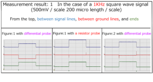
Those who read this measurement result may think that “the measurement of the differential probe may be wrong”, but please refer to the text for the cause of the different measurement result.
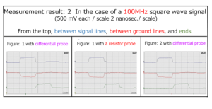
In addition, please see the following experimental results.
Using a coil of enamel wire wound 27 times around a ferrite bobbin as a signal line, connect a capacitor with two 1 cm wide and 2 meter copper foils bonded together with double-sided adhesive tape to the ground wire. The following shows the results of measuring the output waveforms in each case by passing sine waves (1V) of various frequencies in the state of the following “Fig .: 3 to 5“.(500 mV / scale for each 5 μsec / scale)
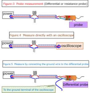
“Figure: 3” shows the case where the end of the output is matched and terminated with a 50Ω resistor and the output waveform is measured with a differential probe and a resistor probe.
“Figure: 4” is the case where the output cable is directly connected to the oscilloscope for measurement.
“Figure: 5” shows the case where one end of a 1-meter-long copper wire is connected to the negative terminal of the differential probe and the other end is led to the ground terminal of the oscilloscope.
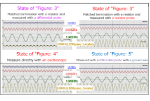
Of the above measurement results, except for State of “Figure: 3”, you might think that the ground wire is always zero volt, but even if you set an element (capacitor in this case) on the ground wire, it has no influence. However, when the matching termination is performed with a resistor and measured with a differential probe in the “state of” Figire:3 “”, the influence of the capacitor set on the ground wire is clearly shown.
It is clear that the hint for elucidating why such a result is obtained is “Measurement with a differential probe with a state ground wire in” State of ” Figure: 5 “”.
I will post the afterword of the book.
Afterword
We still have to see the following commentary based on the recognition that the “ground wire is 0 volt“.
| Single-ended transmission method
A method of connecting with two wires, a signal line and a ground line, and transmitting with a potential difference from the ground (0 volt). Differential transmission method A method in which two signal lines and one ground line (0 volt) are used for a total of three lines, and currents of opposite phases are passed through the two signal lines and transmitted by the potential difference between the signal lines. |
However, if you read this book, I think that the vague concept of the ground has been clarified so far.
In this book, I have always stated that “0 volt ground wire is a misunderstanding”, but I hope you understand.
As described in the preface of this book, even those who read a series of this book series and were surprised that “I did not know until now that electricity travels two wires at the same time with plus and minus” Now that you have confirmed the background that you did not notice the facts, I think that you are fully convinced.
Calling the two lines (a set of conductors) that form a transmission line as a signal line and a ground line is very misleading, so it is necessary to consider those names separately.
For example, M line, W line, etc.
Transmission by one each of the conventional signal line and ground line (that is, M line and W line in the new name) should be differential transmission in nature.
I hope that new ways of using the ground line (W line) will be developed after clearly recognizing the fundamental character.
Of course, the “conventional electrical theory based on the perception that the ground wire is 0 volt” would of course have to be abandoned.
For details, please refer to this book.
table of contents
Chapter 1 Current flows from high potential to low potential
Section 1 Introduction to misunderstandings about grounding
Section 2 Electricity flows from low to high
Chapter 2 Misunderstanding about grounding
Section 1 Existence of pseudo grounding transmission line
Item 1 Is an electric signal transmitted even with a single signal line?
Item 2 Misunderstanding that one ground wire is sufficient
Item 3 Connect the actual coil in parallel to the output terminal of the power supply
Section 2 Existence of pseudo ground wire (when an element is inserted in the ground wire)
Item 1 When a resistor is set on the ground wire
Item 2 When a capacitor is set on the ground wire
Section 3 Relationship between resonant circuit and ground wire
Chapter 3 Cause of misunderstanding that the ground wire is zero volt
Chapter 4 Generation of pseudo-ground wire by electrical measuring equipment
Chapter 5 Harmful effects of grounding when measuring resistance probes
Section 1 Problems when measuring voltage between resistors
Section 2 Measure the relationship between the resonant circuit and the ground wire with a resistor probe
Supplement 1 Relationship between the power supply voltage (Vo) and output voltage (V) of a power supply with an internal resistance of 50Ω
Supplement 2 Transmission line transmission and Ohm’s law
Chapter 6 grounding’s law when measuring various probes
Main measuring instruments used, etc.
1 Pulse generator and function generator
2 oscilloscope
3 Resistance probe
4 Differential probe
4 EO (Electro-Optic-Sampling) probe
5 Coaxial cable
Afterword
| For more detailed information,
please contact: Soubunsha E-mail: info@soubunsha.com 窓文社(Soubunsha)Web site http://u33.sakura.ne.jp/soubunsyamakuji.htm 宇佐美保(Tamotsu Usami) Web site |
Recent Comments