In this book, the consideration in Chapter 11 of “Volume 3 Appearance of Tandem Connections” was insufficient and inappropriate, so further experimental measurements were repeatedly considered. I newly constructed a theory regarding the generation of negative reflected waves in the adjacent transmission line.
As a result, the adjacent transmission line and the signal line / ground line that composes the transmission line also become a transmission line that pairs with the signal line / ground line of the input transmission line.
It was clearly confirmed that the transmission lines were connected in parallel to the input transmission line while having a tandem connection relationship.
Furthermore, I have confirmed that this relationship also occurs in transmission line systems in which a dielectric is inserted between the signal line / ground line of each transmission line.(Generally, a transmission line system in which conductors are arranged on both sides of a glass epoxy substrate)
It was also found that an output signal with a voltage waveform having the same shape as the input signal can be obtained from the adjacent transmission line with a little work, without being limited to a specific frequency.
Furthermore,it was also confirmed that even with only one conductor instead of the adjacent transmission line of two conductors, a current flows through one conductor while being placed in the vortex of the electromagnetic field.
For this reason, you can clearly see that the electric current is not “the movement of electrons or electric charges in the conductor”, but “the electric current is a phenomenon that occurs as a result of the diamagnetic properties of the conductor and the collaborative work with the armature aggregate toward the conductor”. While conducting experimental measurements, we also pointed out the problems of grounding in power supplies that have grounding.
In order to explore the essence of electricity, we must first avoid the problem of grounding (eliminate “grounding”). However, at present, it is generally difficult to eliminate the ground, so in this book, voltage observation is performed using a differential probe (although this is still insufficient).
In this book, I have re-examined “Chapter 11 Consideration on the generation of negative reflected waves in adjacent transmission lines” in “Volume 3, Appearance of Tandem Connections“.
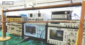
As in the previous work, use four copper round bars with a diameter of 5 mm and a length of 1 meter shown in “Photo: 1” and “Figure: 1” so that the characteristic impedance value of the input transmission line and the adjacent transmission line is 50Ω. Using a transmission line system with the conductor spacing (about 0.7 mm) adjusted, the results of experimental measurements and consideration were supplemented. (Similarly, the conductor spacing between the signal lines of both transmission lines and between the ground lines was set to about 0.7 mm.)
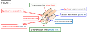
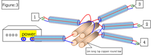
When inputting an electric signal from the power supply (pulse generator) to the input transmission line and measuring the voltage in each transmission line, the tip of the differential probe was touched as shown in “Figure: 3″ below. (The schematic diagram of this transmission line system corresponds to the state where “Fig .: 1” is viewed from the front. “A transmission line” is a transmission line formed by “input / adjacent transmission line signal lines”, and “B transmission line” is a transmission line formed by “input / adjacent transmission line ground lines”.
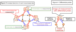
With three sets of transmission lines, “A transmission line”, “adjacent transmission line” and “B transmission line” connected in tandem, the voltage change of each transmission line is measured at the same time to the input transmission line. The fact that they are connected in parallel is demonstrated.
(Note: The simultaneity of each measurement result by one differential probe is ensured based on the time when the trigger current output from the pulse generator together with the input current reaches the oscilloscope.)

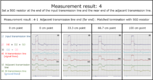
As you can see in this result, as confirmed in the previous book, you can see that
the voltage waveform (voltage value) of the input transmission line in 1) and the total location (that is, 2) of the three voltage waveforms of the A transmission line, the adjacent transmission line, and the B transmission line, which are in a Tandem connection relationship, are equal.
As a background to this, note that among the measurement results of 1) to 6), in particular, the displayed value (3) in the third row from the top of the displayed result is always zero.
(∵ (3)=(1)-(2)=0)
(That is, (1): voltage waveform (voltage value) of “input transmission line” = (2): total value of voltage waveform (voltage value) of each “A, adjacent, B” transmission line )
Of course, on the adjacent transmission line, a voltage waveform having the same shape as the input transmission line and a voltage with a reverse phase waveform that cancels it are also generated.
The following results can be obtained by applying current in the same way with the near and far ends of the adjacent transmission lines open.
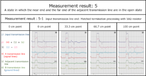
“5) Adjacent transmission line”, “4) A transmission line” and “6) B transmission line” all observe “voltage waveform of the same shape as the input transmission line”, but the voltage of the opposite phase waveform is not generated.
However, in this state, the current generated in the adjacent transmission line cannot be carried out as it is.
But, in the following cases, it can be seen that a waveform with the same shape as the current input to the input transmission line can always be discharged.
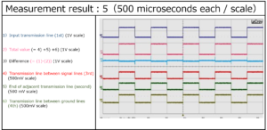
Please see this book for the reason why this happens.
Afterword
transmission lines” in the appearance of tandem connection was insufficient, so by repeating further experimental measurements and reconsidering in this book. , I think that “Construction of tandem connection theory” has been completed.
Furthermore, as considered in “Chapter 6”, it was found that an event resulting from tandem connection occurred in “one transmission line” in addition to the adjacent transmission line.
The following can be seen from the results of these experimental considerations.
If an adjacent transmission line or other conductor is placed under the influence of a group of electromagnetic waves generated in the input transmission line, the newly placed conductor will form a transmission line with respect to the signal line or ground line of the input transmission line.This happens completely independently of “Faraday’s theory of electromagnetic induction“.
Then, it becomes clear that the current flows while maintaining the relationship of tandem connection and the relationship of parallel connection with the current of the input transmission line.
However, the state of these voltages is not clearly indicated by the oscilloscope, which is a conventional general voltage measuring instrument. (For details, refer to “Chapter 7, Section 2, When all terminals are connected to the oscilloscope“)
Faraday’s own words, which were quoted in Volume 3 and did not have as much measurement technology as they are now, are written as follows. “Although all currents always have a magnetic action of appropriate strength at right angles to their flow, a good conductor of electricity is induced in this range of action, and no current is induced in it. It seemed quite strange that it was not done, and that no such current-equivalent effect was perceived. “
And “Faraday’s electromagnetic induction type” became common sense, and even if the current oscilloscope was used by the conventional method, it could not be overturned. Also, the superstition that “ground is always zero volt” has been established and continues to be believed.
Please read this book carefully and say goodbye to the superstitions of “Faraday’s electromagnetic induction” and “ground is zero volt”.
table of contents
Preface
Chapter 1 Current induced in adjacent lines
Introduction: Adjacent transmission lines are transmission lines that are connected in tandem and in parallel.
Section 1 Cause of reverse sign current flowing back from the end of the adjacent transmission line
Section 2 Changes in the current flowing through adjacent transmission lines due to changes in the ends of each transmission line
Item 1 When the near end of the adjacent transmission line is a 50Ω resistor and the end of the input transmission line is open.
Item 2 When the near end of the adjacent transmission line is a 50Ω resistor and the end of the input transmission line is short-circuited
Item 3 When the end of the input transmission line, lined up, and the end of the adjacent transmission line are 50Ω resistors
Item 4 When the input transmission line end is open and the adjacent transmission line end is a 50Ω resistor
Item 5 When the end of the input transmission line is short-circuited and the end of the adjacent transmission line is a 50Ω resistor
Item 6 When a resistor other than 50Ω is set at the end of the input transmission line
Section 3 Confirmation experiment in transmission line system using flat plate
Section 4 Prevention of negative backflow current in adjacent transmission lines
Section 5 Current generation status in transmission lines other than the input transmission line
Chapter 2 Signal waveforms similar to input lines can always be output externally from other transmission lines.
Section 1 Always output from adjacent lines to the outside
Supplement: Cause of the 10KHz waveform slightly deviating from the square wave in “Measurement result: 1 & 2”
Section 2 Development potential for DC transformers
Chapter 3 Actual conditions of crosstalk
Chapter 4 When splitting into an advanced wave and a backward wave
Chapter 5 Wiring with common ground wire (MSL board)
Chapter 6 When one conductor is installed next to the input transmission line instead of the transmission line
Chapter 7 Ground wire hides the essence of electricity here as well
Section 1 One transmission line to the oscilloscope
Section 2 When all terminals are connected to the oscilloscope
Section 3 Harmful effects of earth
Main measuring instruments used, etc.
1 Pulse generator and function generator
2 Oscilloscope
3 SMA connector
4 Differential probe
5 EO (Electro-Optic-Sampling) probe
6 Coaxial cable
7 Parallel line: Red-black covered line
Afterword
| For more detailed information,
please contact: Soubunsha E-mail: info@soubunsha.com 窓文社(Soubunsha)Web site http://u33.sakura.ne.jp/soubunsyamakuji.htm 宇佐美保(Tamotsu Usami) Web site |