If you read the books “Volumes 1 to 5” so far, you can see that the recognition that “light has the dual character of waves and particles” was also the source of all misunderstandings about electricity.
Looking at “Measurement result: 1” on page 21 of “Volume 1, New Current Theory”,
a square wave signal of 20 MHz(for one cycle), which has a transmission time of only 25 nanoseconds ,extends to a state of 2 μs or more, that is, nearly 100 times as an output waveform to the end of a 600-meter cable.
From this result as well, it is difficult to see this 20MHz 1-pulse square wave signal as a single particle, as in the conventional particle theory.
Therefore, in “Volume 1” and later, the 1-pulse square wave signal and the 1-pulse (1 cycle) sine wave signal were also interpreted as an aggregate of “electromagnetic elements” (named by the author), which are quantum entities.
As described in Volume 1, Chapter 7, river waves and ocean waves reflect the “movement of one molecule of water” that composes them. Therefore, if we replace this “one molecule of water” with “one of the armatures”, we should be able to understand the behavior of electromagnetic waves more clearly.
As a result, I found that there is a “Tandem connection” (named by the author) in addition to the conventional “series connection” and “parallel connection” as the connection method of the electric circuit.
Introducing this concept reveals that both capacitors and coils are just “Tandem-connected transmission lines.”
As a result, it became clear that the current flowing through the capacitor and coil has a current flowing in the opposite direction as well as the input current direction.
(Of course, if there is a resistor in the transmission line, there is a current reflection phenomenon due to that resistor.)
Also, in “Volume 5 New Transformer Theory”,
electricity is “proximity action”, so the transformer has no way of knowing
whether the current flowing into itself is “DC” or “AC”, and it turns out that the transformer works without distinction between direct current and alternating current.
(Similar results were obtained for capacitors in Volume 1)
Therefore, traditional electrical theories, especially those that specialize in alternating current, should be reviewed and need to be reconstructed.
As you all know, we are in the age of digital signals (square wave signals)!
Before reading this book, please read the following description, experiments, and calculation results.
“Misunderstanding of AC theory (resonant circuit): AC and direct current are the same electricity”
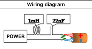
Connect the coil and capacitor in series to the signal line of the coaxial cable connected to the power supply as shown in the figure.
A terminating resistor (50Ω) was set at the output end of the coaxial cable, and measurement was performed with a differential probe. As a result, I confirmed the occurrence of the resonance phenomenon in the square wave signal.

The following shows the measurement results of the output waveform when one pulse each of a 500KHz square wave signal and a sine wave signal (27.8KHz sine wave as a reference for the total result) is input to the circuit shown above. The result of adding up the output of the 500KHz square wave by the calculation software Excel is also shown below.This is the Excel method used in “Volume 5” and “Volume 1”.
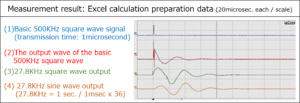
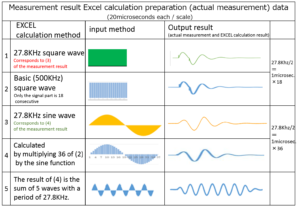
Looking at the result of this Excel, it becomes clear that “the result of continuous summing of the output waveform of the 500KHz square wave signal based on this time every 1 microsecond“, “27.8KHz square wave“ and “the result of multiplying the output waveform of the basic square wave by the sine function every 1 microsecond and adding it up.“ match “Measured value of sine wave output waveform“.
You might wonder, “Even if it matches the actual output waveform of a 27.8KHz sine wave, something is wrong because its shape looks different from the sine wave?“
The result of “The result of (4) is the sum of 5 waves with a period of 27.8KHz.”in the above measurement results clearly shows the sine wave shape at the summed points.
Of course, the same measurement results and calculation results can be obtained when “capacitors and coils are connected in parallel”.
The so-called “resonant circuit” is a misunderstanding even in the case of parallel connection.
As in the case of series connection, connect the coil and capacitor in parallel to the signal line of the coaxial cable connected to the power supply as shown in the figure below.
Set a terminating resistor (50Ω) at the output end of the coaxial cable.
With this device, as in the case of series connection, the output waveform when one pulse each of the basic 500KHz square wave signal and sine wave signal (27.8KHz sine wave as a reference for the total result) is input is differential. The result measured by the probe is shown. Here, the 1-pulse sine wave output wave does not have the shape of a sine wave.

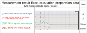
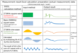
Looking at the result of this Excel, it can be confirmed that the total result of the output waveform of the basic 500KHz square wave signal matches the measured value.
As you can see, the so-called “resonance phenomenon” is not a phenomenon peculiar to “AC: sine wave” regardless of whether it is connected in series or in parallel.
That is, alternating current and direct current are the same electricity.
Preface
Chapter 1 AC theory is the world of calculation
Section 1 Fracture of exchange theory
Section 2 Current and voltage phase shift is a misunderstanding
Section 3 Misunderstandings about resonant circuits
Item 1 Backflow current is generated from the capacitors and coils.
Item 2 When the capacitor and coil are connected in series
Item 3 When resistance is also involved
Item 4 Multiple reflection between each element and the length of the coupling part
Item 5 When a capacitor and a coil are connected in parallel
Item 6 Misunderstanding of LC circuit
Item 7 Coil (capacitor) characteristics are correlated with input / output transmission lines.
Chapter 2 Both the skin effect and Kelvin’s equation are misunderstood
Section 1 Proof that the skin effect is misunderstood
Supplement: 1 Multiple reflection phenomenon
Supplement: 2 Even now, in the age of experimental science
Section 2 Kelvin’s equation is also misunderstood
Supplement: 1 Relationship between the power supply voltage (V0) of a power supply with an internal resistance of 50Ω and the output voltage (V)
Supplement: 2 Presence or absence of frequency dependence of the flow of electrical signals
Section 3 Reconfirm multiple reflections in plus / minus waves
Chapter 3 Personal view of TV radio waves and X-rays
Afterword
| For more detailed information,
please contact: Soubunsha E-mail: info@soubunsha.com 窓文社(Soubunsha)Web site http://u33.sakura.ne.jp/soubunsyamakuji.htm 宇佐美保(Tamotsu Usami) Web site |
Great weblog here! Also your web site lots up fast!
What host are you the usage of? Can I am getting your associate link on your host?
I want my web site loaded up as quickly as yours lol
Asking questions are in fact fastidious thing if you are not understanding anything completely, but this paragraph provides
fastidious understanding even.