“Faraday Electrical Experiment (Vol. 1) by M. Faraday, Supervisor: Toyosuke Tanaka” has the following description.
| Even if a good electric conductor is placed in this working range, no current is induced in it.
It is strange that no effect equivalent to such an electric current is detected. Considering these results, that is, expecting to obtain electricity from ordinary magnetism, encouraged me in various cases for the experimental study of the sensitive effect of electric current. And recently I was able to reach a positive result. |
When one pulse of a square wave signal was sent to the “capacitor or coil” in the state shown above, the following measurement results were obtained.
There was no way to know the existence of “electromagnetic waves” in Faraday,
which was before “Maxwell’s prediction of electromagnetic waves”.
In an attempt to obtain electricity from normal magnetism later in this quote, he would have focused on “magnetism only”.
Nevertheless, this attempt, apart from Faraday‘s initial expectations, evolved into a “great achievement” that created a practical “tranceformer” prototype. (See later “Chapter 9 Faraday’s own Trance Experiments” on this subject.)
Of course, as I have experimentally considered so far, “Faraday’s law of electromagnetic induction” is a product of misunderstanding, so the principle of transformer is naturally irrelevant to “Faraday’s law of electromagnetic induction”.
If the coil of the transformer is unwound, the wire is in a short state, but why does the transformer not emit fire? This has been a question I have had since I was a student.
When a square wave (direct current) with a frequency of 0.1 Hz (period is 10 seconds and transmission time is 5 seconds) is input to the transformer, the voltage at the coil entrance / exit of “Measurement result: 1” in “Chapter 2” later. Is 0 volt, so it is a fact that it is in a short state.
Since the input voltage in this experiment was 1 volt, the fire did not blow, but if it was 100 volt, it would have been a serious accident.
In this book, I will clarify whether the transformer that we use every day does not emit fire and functions properly as a transformer.
Before reading this book, please read the following description, experiments, and calculation results.
Transformer operation is basically direct current (square wave signal)
When only one pulse (1V / 0V) of a square wave with a different frequency is input to the primary coil of the transformer, the voltage waveform of the same shape as shown below can be obtained at the same time as the measurement result.
The measurement results of 0.1Hz, 10Hz, 50Hz, 250Hz, and 500Hz are shown in order from the top.
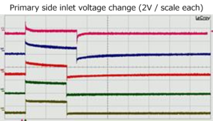
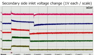
Furthermore, if the unit of the time axis is unified to 10 milliseconds per scale so that the entire 10 Hz (square wave) signal of one pulse is displayed, the following measurement results can be obtained.

From this measurement result, it can be seen that the operation of the transformer on the square wave signal is equivalent to the event that the DC input is stopped at a certain time during the operation by the DC input.
And if the input is restarted immediately after stopping the DC from this phenomenon, the DC input will be continued, and this operation will have the same result no matter how many times it is done..
Therefore, it is possible to synthesize a long-period square wave signal such as “Graph: 2” from the result of the short-period square wave shown in “Graph: 1” as shown below. Furthermore, it is also possible to synthesize a sine wave signal such as “Graph: 3”.
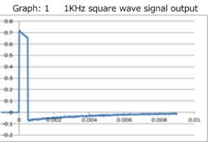
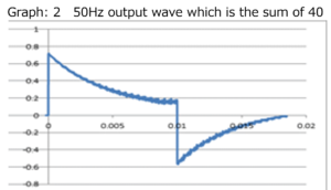
In “Graph: 3”, when adding up 36 pieces, the basic voltage value in Graph 1 is sin10 ° for the first pulse, sin20 ° for the second pulse, sin30 ° for the third pulse, and sin360 ° for the 36th pulse. The calculation was performed by multiplying the sine values in sequence.
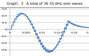
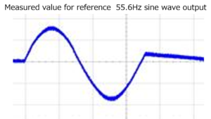
For reference, “measured value for reference” is also shown, but good matching with the total value is recognized.
Now, I will post a part of Chapter 10 of this book.
Chapter 10 Measurement Results on Copper Round Bar Transmission Lines Connected in Columns
In order to further solidify the theory that “the fundamental principle of transformers is columnar connection”, which has been elucidated in this book, “Chapter 11 Supplement: 3 Inputs and Adjacent” in the separate volume “Volume 3 Appearance of Columnar Connections” ,the experimental results shown in “When the terminal state of the transmission line is changed” are shown below.
Please refer to the separate volume “Volume 3” for details such as consideration of why such experimental results are obtained.
The experiment is carried out on an input transmission line as shown in “Fig. 1” consisting of four copper round bars with a length of 5 mm and a length of 1 meter, and an adjacent transmission line connected in tandem to the input transmission line.
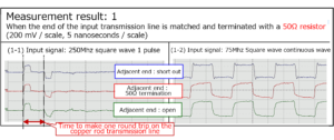
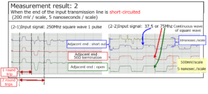
In the experiment, when the end of the input transmission line was matched and terminated with a 50Ω resistor, it was changed to three states: a short state and an open state, and the end treatment of the adjacent transmission line was also shorted accordingly. It is performed by changing to the 50Ω termination processing state and the open state. In each case, a continuous wave of 250MHz (1V / 0V) 1-pulse square wave and 75MHz (in some cases 37.5MHz) square wave is input from the pulse generator to the input transmission line, and the near end of the adjacent transmission line. The voltage change of the part was measured with a differential probe, and the following results were obtained.

First, the measurement results for the transmission line shown in “Figure: 1” when the end of the input transmission line is matched and terminated with a 50Ω resistor are shown.
Next, the following shows the measurement results on the adjacent transmission line when the end of the input transmission line is short-circuited.
The last is the measurement result on the adjacent transmission line when the end of the input transmission line is open.

The following can be seen from these measurement results.
There is a phenomenon in which a current of the same shape as the input current is induced by the current input to the input transmission line to both the near end and the far end of the adjacent transmission lines that are in a columnar connection relationship.
The current toward the far end flows back as a negative or positive current depending on the conditions at the far end of the input transmission line and the adjacent transmission line.
If the end of the input transmission line is not terminated, the backflow current generated in the input transmission line causes a new current to be generated in the adjacent transmission line at the input section of the input transmission line.
These phenomena are caused by the columnar connections that have been experimentally considered so far, and are equivalent to the “considerations regarding the generation of negative reflected waves in adjacent transmission lines” discussed in this chapter.
Of course, depending on the terminal condition of the input transmission line or the method of eliminating the column connection, a positive wave may be generated instead of a negative reflected wave on the adjacent transmission line.
From such a simple experiment and an experiment of the transmission line structure including the case where the ends of the input transmission line and the adjacent transmission line are short-circuited like the coil, it becomes clear that the basic principle of the transformer is the column connection.
table of contents
Preface
Chapter 1 Contradiction between transformer operation and “Faraday’s law of electromagnetic induction”
Chapter 2 Transformers also work with square wave signals
Chapter 3 Check the operating status of the transformer with a square wave signal
Chapter 4 Transformer operation is basically a DC signal (square wave signal)
Chapter 5 Confirm the operation of the transformer based on the DC signal (square wave signal) with calculation software
Chapter 6 Similarity between a single coil and a transformer
Chapter 7 Reconfirmation of similarity between transformer and single coil
Chapter 8 Measurement results using another transformer
Chapter 9 Relationship between transformer and continuous wave
Chapter 10 Measurement Results on Copper Round Bar Transmission Lines Connected in Columns
Chapter 11 Examination of general electric wires as circular transmission lines
Chapter 12 Coil general electric wires
Chapter 12 Section 1 Multiple coil effects
Chapter 12 Section 2 Effects of core materials
Chapter 13 Faraday’s own trance experiment
Chapter 14 Role of core materials in transformers
Chapter 14 Section 1 When ferrite is used for the transformer core
Supplement: Measurement of only the positive terminal of the differential probe
Chapter 14 Section 2 Effect of ferrite on transmission lines
Chapter 14 Section 3 Preliminary Experiments Using Permalloy
Chapter 15 Relationship between transformer input / output voltage and coil turns ratio
Chapter 16 An example of general recognition of transformers
Chapter 17 Transformer power loss
Chapter 17 Section 1 Loss inside the transformer
Chapter 17 Section 2 Loss during power transmission
Chapter 18 DC transformer
Afterword
| For more detailed information,
please contact: Soubunsha E-mail: info@soubunsha.com 窓文社(Soubunsha)Web site http://u33.sakura.ne.jp/soubunsyamakuji.htm 宇佐美保(Tamotsu Usami) Web site |